In previous article series I provided an overview and step by step instruction how to make you Bellfire fireplace with Mertik Maxitrol controller smart. This project that was presented during the Home Assistant Conference 2020.
In the article series and presentation I focused on the essential controls, basically turning the fireplace on and off. I received number of requests to extend the controls to support increasing and decreasing the fire and also activating the so called center burner.
After doing some research and trial and error I’ve found the combinations for the relays to add these features to your smart fireplace.
This article provides you with an overview and links of all articles published around the Bellfire fireplace (Mertik Maxitrol controller) project that was presented during the Home Assistant Conference 2020.
Although this solution is presented around Home Assistant you can easily use the same solution in OpenHab, Domoticz or any other open home automation platform.
The wiring is now ready, let’s expose three switches to Home Assistant to control the relays.
Expose pins as switches
Open ESPHome and click EDIT on your node. The ESPHome configuration editor will now show. Add following configuration in the bottom of the configuration.
Note: The PIN name is translated from the physical D number printed on the ESP to the addressable name used in configurations and programming. E.g. pin D7 is referred to as GPIO13, all mappings can be found in the image in the ESP Intro section.
UPDATE (thanks Petr): “Fortunately ESPHome knows the mapping from the on-board pin numbers to the internal pin numbering, but you need to prefix the pin numbers with D as in the image below in order for this automatic mapping to occur. In general, it is best to just use the D0, D1, … pin numbering to avoid confusion”
We are adding three switches of the platform type GPIO, this means that the switch will 1:1 control the GPIO pins. For every switch we define the GPIO pin that is controlled, and we provide a name and ID.
Flash the firmware Over The Air (OTA)
That’s it, now flash the firmware of the ESP with the updated firmware based on our new configuration. We do not need to use the flasher tool anymore, we can use the Over-The-Air flash feature to flash the chip with the new firmware over the WiFi Connection. It is as easy as clicking the UPLOAD button.
ESPHome will compile the new firmware, send it over to the ESP that will than flash itself. After flashing the ESP will come back online with the new firmware. It does not get much easier!
Control the relay from Home Assistant
Wait till the ESP has been flashed successful and is connected to the WiFi.
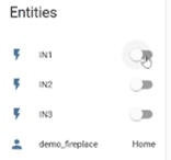
Find your device in Home Assistant, noticed that the device now has 3 entities. Click on the device and you’ll see that it has three switches, called IN1, IN2 and IN3.
Press the switches and enjoy the sound of clicking relays. Every switch should control the matching relay.
Create timing to control the fireplace
To control the fireplace I need to match following sequences with the switches:
Ignition, close contacts 1 and 3 simultaneously for 2 seconds
Fire off, clos contact 1,2, and 3 simultaneously for 1 second
We need to control the relays in these sequences with the ESP board. We can do this by extending the ESP configuration. We’ll add an Ignition switch that will execute sequences above when turned on and off.
Open ESP home and click edit on the node to go to the configuration editor.
Add a new Switch (right under IN3) with following configuration.
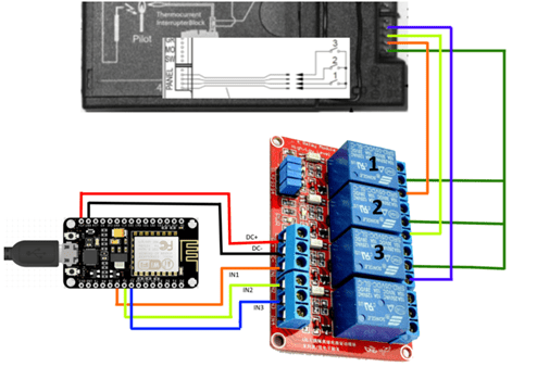
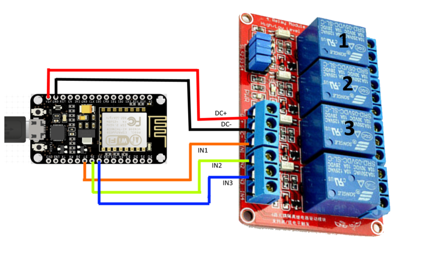
To control the relay we need to provide high or low power to the IN ports of the board. This board has four relays. In my example I only need to use three relays.
Wiring the relay board to the ESP is easy. I always use Dupont cables and mini breadboards, this way soldering is not required.
Powering the relay board
The relay board needs 5v power. We will power the relay board directly from the ESP using the 5v VIN pin.
Controlling the relays
Pin D5, D6, and D7 will be used to control the three relays on the board.
Make sure you have some ESP boards ready to go, you can buy ESP boards few dollar on AliExpress. Buy the ESP32 variant if you need Bluetooth (BLE) connectivity.
Now we need to load the configuration of your node to the ESP board. I recommend flashing the firmware from your local laptop and a USB cable, using the Flasher tool from ESPHome. Let’s get started.
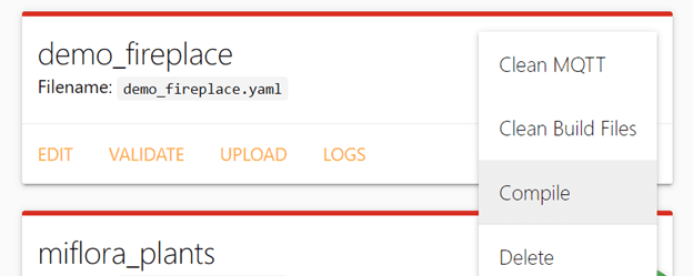
Compile firmware
We need to start by compiling the firmware that we’ll use to flash the ESP chip. In ESPHome select the menu of your node (three dots (…) in the top right of your node) and select Compile.
ESP home will now compile your firmware. After the compilation is finalized you can download the firmware. Download and store the file somewhere you can find it later on.
Flash ESP with compiled firmware
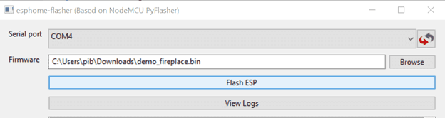
Now we’re going to flash the ESP firmware with your compiled firmware.
Serial port: select COM port where the board is connected (there is probably only one option 😊).
Firmware: Browse to the location where you downloaded your compiled firmware and select your firmware.
Click Flash ESP and wait
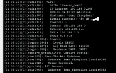
The ESP will be flashed now, you can follow the progress in the console window. When finished writing the firmware the ESP will restart and connect to your WiFi.
The ESP will be ready after it states that it’s ready for Over-The-Air Updates and that he API server is ready.
All good so far, now configure the device in Home Assistant.
Configure device in Home Assistant
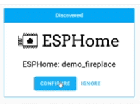
Home Assistant will automatically recognize the ESP on the network and notify you about the new device found. Click on the notification or click Configuration, Integrations. Find the new discovered device and click configure.
Provide the OTA password that you set during step 3 when you created the node in ESPHome.
Home Assistant will now add your ESP as a new device, there is not much you can do with the device as there are no entities to control.
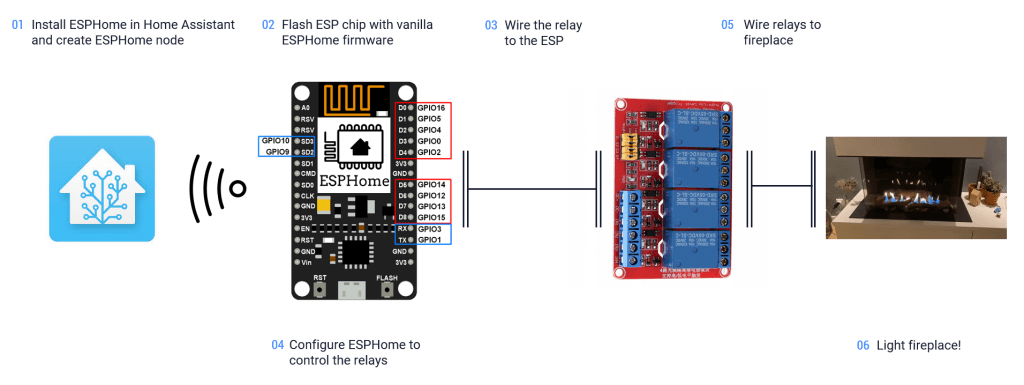
We now have all ingredients for our solution, covered in the in the previous articles in this series. Before we start building, let’s take a look at how this all will work together end-to-end.
Home Assistant, as home automation platform and for user interactions and automation
ESP chip low cost connected controller hardware, providing GPIO pins to control the relay and WiFi connectivity
ESPHome software that run’s on the ESP, providing the ability to configure actions with the relay and communication with Home Assistant.
Relay board with multiple relays that can control switches providing high or low power as input
In six simple steps we’ll make the fireplace smart.
Install ESPHome in Home Assistant and create ESPHome node