
This article is part of the Make your Bellfire fireplace smart project that I presented during the Home Assistant Conference 2020.
It’s time to execute the fourth step, you can find all steps in the overview how it all going to work article.
The wiring is now ready, let’s expose three switches to Home Assistant to control the relays.
Expose pins as switches
Open ESPHome and click EDIT on your node. The ESPHome configuration editor will now show. Add following configuration in the bottom of the configuration.
switch:
  - platform: gpio
    pin: GPIO13   #D7
    name: "IN1"
    id: IN1
  - platform: gpio
    pin: GPIO12  #D6
    name: "IN2"
    id: IN2
  - platform: gpio
    pin: GPIO14  #D5
    name: "IN3"
    id: IN3
Note: The PIN name is translated from the physical D number printed on the ESP to the addressable name used in configurations and programming. E.g. pin D7 is referred to as GPIO13, all mappings can be found in the image in the ESP Intro section.
UPDATE (thanks Petr): “Fortunately ESPHome knows the mapping from the on-board pin numbers to the internal pin numbering, but you need to prefix the pin numbers with D as in the image below in order for this automatic mapping to occur. In general, it is best to just use the D0, D1, … pin numbering to avoid confusion”
We are adding three switches of the platform type GPIO, this means that the switch will 1:1 control the GPIO pins. For every switch we define the GPIO pin that is controlled, and we provide a name and ID.
Flash the firmware Over The Air (OTA)
That’s it, now flash the firmware of the ESP with the updated firmware based on our new configuration. We do not need to use the flasher tool anymore, we can use the Over-The-Air flash feature to flash the chip with the new firmware over the WiFi Connection. It is as easy as clicking the UPLOAD button.
ESPHome will compile the new firmware, send it over to the ESP that will than flash itself. After flashing the ESP will come back online with the new firmware. It does not get much easier!
Control the relay from Home Assistant
Wait till the ESP has been flashed successful and is connected to the WiFi.
Find your device in Home Assistant, noticed that the device now has 3 entities. Click on the device and you’ll see that it has three switches, called IN1, IN2 and IN3.
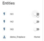
Press the switches and enjoy the sound of clicking relays. Every switch should control the matching relay.
Create timing to control the fireplace
To control the fireplace I need to match following sequences with the switches:
- Ignition, close contacts 1 and 3 simultaneously for 2 seconds
- Fire off, clos contact 1,2, and 3 simultaneously for 1 second
We need to control the relays in these sequences with the ESP board. We can do this by extending the ESP configuration. We’ll add an Ignition switch that will execute sequences above when turned on and off.
Open ESP home and click edit on the node to go to the configuration editor.
Add a new Switch (right under IN3) with following configuration.
- platform: template
    name: "Fireplace_ignition"
    id: Fireplace_ignition
    turn_on_action:
      - then:
        - switch.turn_on: IN1
        - switch.turn_on: IN3
        - delay: 2s
        - switch.turn_off: IN1
        - switch.turn_off: IN3
        - switch.template.publish:
            id: Fireplace_ignition
            state: ON
    turn_off_action:
      - then:
        - switch.turn_on: IN1
        - switch.turn_on: IN2
        - switch.turn_on: IN3
        - delay: 1s
        - switch.turn_off: IN1
        - switch.turn_off: IN2
        - switch.turn_off: IN3
        - switch.template.publish:
            id: Fireplace_ignition
            state: OFF
Press the Upload to compile, upload and flash the ESP with the new firmware. Test your new switch and verify that the relay react as expected.
Now it’s time to for the last step, time to wire the relays to the fireplace.