This article will provide you with a walkthrough on how you can build a water usage meter sensor that integrates with your Home Assistant for under 10 $/EURO without the need for any soldering or coding skills.
This article will also cover the configuration that’s needed in Home Assistants to translate the ‘pulse’ to liters (or any other non-metric measurement) in Home Assistant. In the end you will have clear insights in how much water you are using per day, hour, and week.
Why do you want to measure water usage of your home?
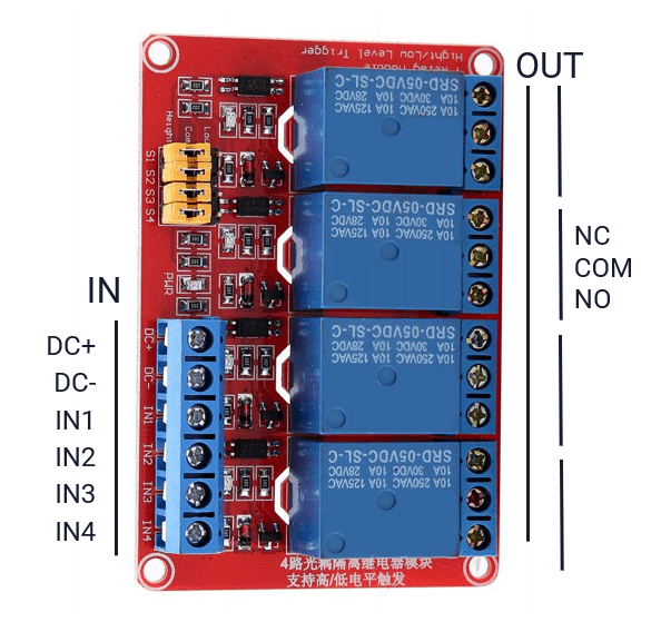
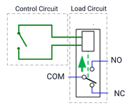
These days it’s all about insights. I measure pretty much all my utilities, including power and city heating. The last missing piece is water usage. Although the water in the Netherlands is not really expensive, I wanted to get more insights into how much water we are using and if there is any way to save some water. Unfortunately, water delivery doesn’t come with a smart meter. There’s just an analog counter. So how do you measure the water usage and make this analog meter smart?
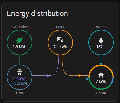
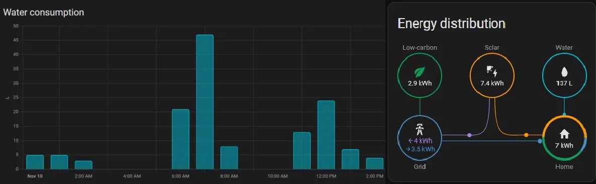
See water usage in the Home Assistant Energy Dashboard
The 2022.11 release of Home Assistant added the option to track water usage in the Home Assistant Energy dashboard. The ESPhome configuration has been updated to support this feature. Thanks to MJV for sharing his configuration on the Home Assistant forums.